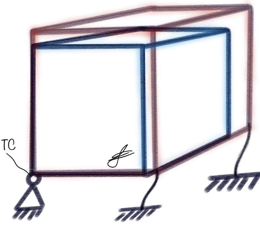
Thermal center of a 3D body suspended on springs
part of the Opto-Mechanical Toolkit
Calculation Tool FunctionalityThis tool offers a comprehensive analysis of a suspended 3D rigid body subjected to thermal expansionforces. The tool accepts various inputs, including:
For user convenience, the inputs section provides the option to plot, which can be easily
accessed using push buttons to expand the relevant sections.
To prevent misinterpretation it is adviced to use the SI unit system. Direction
vectors are automatically normalized in the background. |

|
||||||||
| Mind that error handling is limited. Make sure all input are numerical values. Tooling is not yet overly benchmarked so usage at own risk. | |||||||||
|
|
|||||||||
|
linear spring direction vectors [kx ky kz] |
spring application points [px py pz] |
spring stiffness in spring direction |
|||||||
|
|
Red line representing spring directions, blue dot indicating interface points. Green dot representing World Coordinate System | ||||||||
|
torque spring direction vectors [Tx Ty Tz] |
torque stiffness around direction vector |
CTE [m/K] |
ΔT [K] |
||||||
|
|
Red line representing Torque rotation axis towards [0,0,0]. Green dot representing World Coordinate System [0,0,0]. | ||||||||
|
CALCULATION RESULTS
|
|||||||||
|
|
|
|
|||||||
Body rotation in WCS |
Thermal center location |
||||||||
|
|
|||||||||